
Frequently Asked Questions (FAQ) on Power Quality
Power Quality – Power Factor (P.F.) and Harmonics
The poor Power Factor of electrical loads is a common problem for all the industrial companies. Improving the power factor is vital for improving the power quality. Every user who utilises electrical power to obtain work in various forms continuously asks the mains to supply a certain quantity of active power together with reactive power. Most loads on an electrical distribution system can be placed in one of three categories.
• Resistive
• Inductive
• Capacitive
The most common of these on modern systems is the inductive load. Typical examples include transformer, fluorescent lighting, A.C. induction motors, Arc/induction, furnaces etc. which draw not, only active power from the supply, but also inductive reactive power (KVAr). Common characteristics of these inductive loads are that they utilise a winding to produce an electromagnetic field which allows the motor or transformer to function and requires a certain amount of electrical power in order to maintain the field. Therefore Active Power (K.W.) performs the work, whereas Reactive Power (KVAr) sustain the electromagnetic field. This reactive power, though is necessary for the equipment to operate correctly but could be interpreted as an undesirable burden on the supply.
Power Factor (Cosφ )
The power factor Cosφ of a load is defined as the ratio of active power to apparent power i.e.
Apparent power is a combination of reactive & active power. The closer cosφ is to unity; the less reactive power is drawn from the supply.
Power factor system is a significant consideration in the electrical design layout of any installation. Its rating, design, and location can significantly impact power losses, voltage drops, peak demand, utilization of transformer and conductor capacity, and utility bills. With many electrical distribution companies adopting KVAH billing scheme from earlier KWH billing, maintaining the right pf (neither leading nor lagging) affects the KVAH unit consumption and reduces electricity bills. Moreover, characteristic of loads used in installation plays a vital part in designing and implementing the right PF solution.
Use of capacitor banks is one the oldest and a standard method used for compensating reactive power for improved power factor. Further advancements in IGBT technologies have resulted in Static Var Generators (SVGs) and Active filtration. Dynamic, fast switching loads and Harmonic generating Non-linear loads requires special attention in designing the right PF solution and optimum switching / Hybrid technologies.
Another significant aspect to be considered in the modern installation is extensive use of harmonic generating Non-linear loads. Depending on the density of such loads, it can cause high current and voltage distortions (THD-I and THD-V) resulting in breakdowns and array of operational problems. Using any capacitor bank in fixed or automatic mode in such installation can further increase RESONANCE issues, resulting in failure at the capacitor bank-level, distribution equipment, and sensitive loads. Such practice of using a capacitor bank without understanding network behavior and characteristics should be avoided.
Under the above circumstances, meaningful PF and harmonic study of installation assume significance. Advanced power quality analyzers carry out the studies at various locations by switching ON and OFF the existing capacitor banks. Harmonic distortion and variation of loads are recorded. Other network information like SLD, transformer ratings, DG ratings, impedances, and the network’s fault level are collected.
The data thus collected is then simulated in advances analytical software to decide the following:
- Rating of PF and Harmonic mitigation solution
- Location of systems
- Type of system like pure RTPFC, Passive Tuned or Detuned, Hybrid with Active filtration
NAAC ENERGY OFFERS COMPREHENSIVE PF AND HARMONIC STUDIES

There are many objectives to be pursued in the planning of an electrical system. In addition to safety and reliability, it is imperative to ensure that electricity is appropriately used. Each circuit, each piece of equipment, must be designed to guarantee the maximum global efficiency in transforming the source of energy into work.
Among the measures that enable electricity use to be optimised, improving the power factor of electrical systems is undoubtedly one of the most important.
If we quantify this aspect from the utility company’s point of view, raising the average operating power factor of the network from 0.7 to 0.9 means:
• Cutting costs due to ohmic losses in the network by 40%
• Increasing the potential of production and distribution plants by 30%.
These figures speak for themselves: it means saving hundreds of thousands of tons of fuel and making several power plants and hundreds of transformer rooms available.
Thus in the case of low power factors, utility companies charge higher rates in order to cover the additional costs they must incur due to the inefficiency of the system that taps energy.
It is a well-known fact that electricity users relying on an alternating current – except for the heating elements – absorb from the network not only the active energy they convert into mechanical work, light, heat, etc. but also inductive reactive energy whose primary function is to activate the magnetic fields necessary for the functioning of electric machines.
The power factor is thus the ratio between active power and apparent power (vectoral sum of active and reactive power), an indicator of the quality of a facility’s electric system since the lower the power factor is, the higher the inductive reactive component will be in relation to the active component.
It is possible to produce reactive energy, where necessary, by installing power capacitors or automatic power factor correction systems. Capacitors absorb a current that is 180% out of phase with the inductive reactive current; the two currents are algebraically summed together so that circulating upstream from the point of installation of the capacitor is a reactive current that is equal to the difference between the inductive and capacitive currents.
The exchange occurs between the capacitor and user; this is why we say that the capacitor supplies reactive energy to the user.
Power flows with and without power factor correction
Theoretically speaking, when you must choose where to locate the capacitive power the most appropriate solution from a technical standpoint would be to assign each load its own power factor correction capacitor, to be switched on together with the machine.
In practice, however, this entails high costs and technical problems in most cases, since it requires the installation of a larger number of low-power capacitors distributed in many different points, which cannot be effectively monitored over time; plus little benefit is to be derived from reducing losses in the cables, negligible compared to those in the power transformer. Therefore, this solution is only feasible in large facilities or where there are very high power loads.
The most appropriate power factor correction system thus consists in the installation of an automatic capacitor bank on the bus bars of the distribution panel and, if necessary, fixed capacitor banks for correcting the power factor of the transformer, asynchronous motors and any loads absorbing considerable quantities of reactive power.
The automatic system of the capacitor bank has the task of switching in the necessary capacitance according to the load requirements at each given moment.
Calculating the dimensions of the capacitor bank you need to install in your system is very simple: note the cos of the system without power factor correction and the cos you want to obtain, and it will take just a few calculations to derive the reactive power necessary in order to reach the desired power factor. The power factor can differ greatly between two users because it depends both on the type of equipment installed and how it is used.
For example, asynchronous motors – by far the most widely used, though brushless motors actuated by static AC/DC or AC/AC converters have been gaining popularity in recent years – have a power factor that varies greatly according to the motor load and type of construction and can reach very low values in the absence of loads. Similar observations may be made with respect to transformers. For all these types of electric machines, recourse is often made to a fixed power factor correction at the motor or transformer level. Other significant differences can be seen in electrical equipment such as lamps, furnaces, welding machines and converters.
Calculating of reactive power necessary power factor correction
P = active power of the system
cosφ0 = cosφ of the system without power factor correction
cosφ1 = cosφ you want to bring the system toQc = reactive power of the power factor correction system to be installed
k = cosφ0 and cosφ1, this data is derived from the table (next page)
Qc = P(tanφ0 – tanφ1) =P.K
Correcting the Power Factor of MV / LV Transformers
It is always a good idea to ensure a power factor correction for MV / LV transformers since even when they are operating loadless (e.g. during the night) they absorb reactive power, which must be compensated. The exact capacitor power necessary may be calculated using the formula below:
Q = Io% * Pn / 100
Io = loadless current (specified by the transformer manufacturer)
Pn = rated power of the transformer
Where alternatively, if the required data is not available, you can refer to the table below, which differentiates among types of transformers with NORMAL losses.
Reactive power for CORRECTING the POWER FACTOR CORRECTION NO LOAD of 50hz three-phase transformation MV/LV(KVAr)

General information
Modern manufacturing plants are characterised by the use of highly dynamic machinery, like welding loads. Alongside the undisputed advantages of today’s modern techniques, there is, however, the disadvantage that the mains supply networks are often affected by frequent load fluctuations and harmonic oscillation. It often leads to unstable stress ratios. Flickering, excessive current and increased losses in energy distribution. This reduces not only the supply capacity but also impairs the function of sensitive electronics controls.
Conventional reactive power compensation systems are designed for optimising the power factor and reducing the level of harmonic oscillation but offer no satisfactory solution for frequent load fluctuations. The range of application of these units is the compensation of static as well as fluctuating loads with switching cycles measured by minutes.
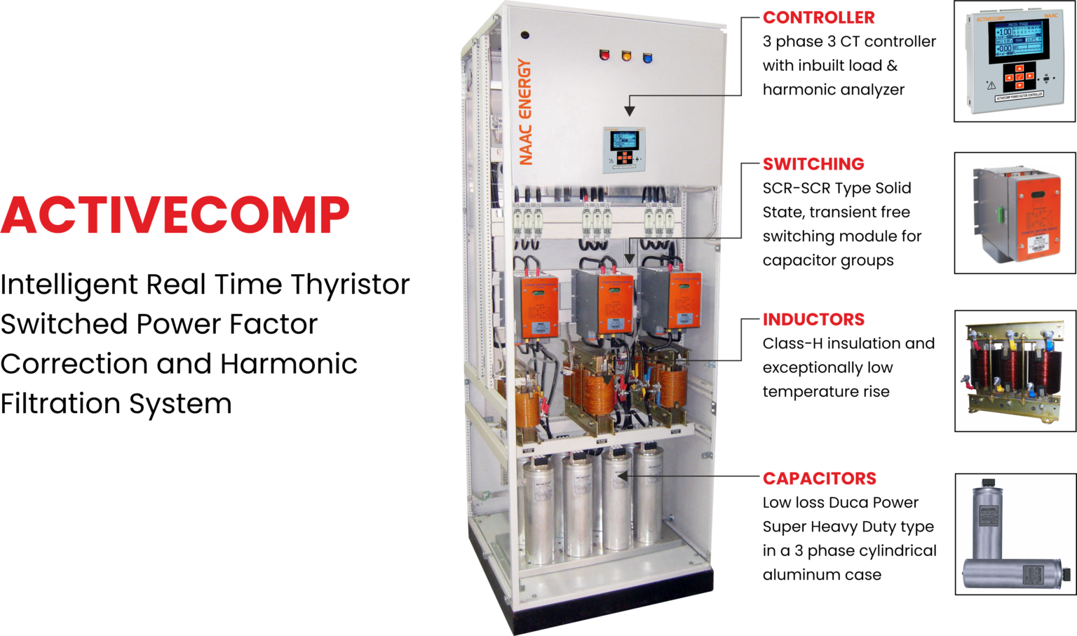
ACTIVCOMP
• At each moment optimised cosφ
• Soft switching without transients
• Flicker eliminated
Application
The real-time power factor compensation equipment of series ACTIVECOMP offers a solution. In these assemblies, the classic components controller and air contactor are substituted by a combination of corresponding high-speed controller and thyristor power modules type ACTIVECOMP. This system reacts immediately on load fluctuation, and reactive power surges will be neutralised in the supply network. The power factor is optimised at each moment, on cycle to cycle basis, typical response time less than 20 ms. The adverse effects described above are reduced to a minimum. This gives the consumer not only the advantage of a stable supply ratio but the ability to minimise energy distribution and reduce costs. To increase the switching performance to an optimum, the control signal for the steering of the capacitor banks can alternatively be given directly by the logic control of bigger loads.


Coefficient K by which to multiply the active energy consumed in KW in order to determine the KVAR necessary for correcting the Power Factor (Cosφ1 is the initial PF obtainable with correction),
Recommender final Cosφ = 0.95 up to 1.00

Fast and Accurate Compensation
The ACTIVECOMP is a Transient Free Fast Compensation System. It is used for Power Factor Correction & Harmonic Filter. The compensation is based on averaging the FFT analysis of each cycle, resulting in more accurate compensation, even in the presence of harmonics.
Simultaneous Group Connection
When load changes require connection or disconnection of more than one step, the ACTIVECOMP controls the switching of as many steps as required precisely at the same time. Simultaneous connection or disconnection provides the benefit of fast full compensation. For e.g., with 1:2:2 system configuration and groups 1 & 2 are connected. When one more step is required, group 3 will be connected simultaneously, while group 1 is disconnected. Real binary sizing – 1:2:2 is precisely the same as 1:1:1:1:1.
Transient-free Switching
Electronic switching technology prevents any transients typically associated with conventional capacitor switching. This is extremely important in sites with sensitive electronic equipment, such as hospitals, data centers and facilities.
Fixed Capacity & Filter Characteristics
The capacity of the ACTIVECOMP capacitors is virtually permanent over the years, which prevents the need to replace capacitors. Moreover, the tuning frequency remains constant over time, which allows system performance to remain at the highest possible level.
There is an ongoing cumulative reduction of capacity in electromechanically switched PFC systems due to the effect of transients during connections and disconnection. This can be detrimental to detuned electromechanically switched systems where the changes in the ratio between the capacitors/reactors shift the resonance frequency, which may result in resonance. The Activcomp prevents these conditions.
Long Life and Reduced Maintenance Costs
NAAC ACTIVECOMP reduces site maintenance costs by increasing the lifetime of:
• Switching elements
• Capacitors
• Sensitive electronic equipment
Capacitor Duty Cycle-SCAN Mode
The unique SCAN feature protects the ACTIVECOMP capacitors & reactors, increases their life span. Simultaneous connection and disconnection of steps in FIFO (First In First Out) manner is shown in the diagram on the previous page.
The scan feature reduces the average current in the capacitors and the reactors and therefore providing the following advantages:
• Reduces substantially the increase of temperature in these elements resulting in longer life expectancy of the inductors and capacitors.
• Reduces the effect of over-current and over-voltage caused by the harmonics on the capacitors and inductors.
• The tuning frequency of the de-tuned filter or tuned filter is stable since the capacitor value (microfarad)
doesn’t change due to the low temperature achieved by the scan mode.
Easy to Use and Maintain
The advanced DSP and microprocessor-based controller, with its large full graphic LCD display, provides easy-to-use operation. The controller includes a complete electrical measurement system, which can replace a facilities main monitoring meter. The controller operates the BIT (Built-In Test), which reports system or network conditions. The optional PowerlQ software can remotely control all ACTIVECOMP operation and display additional system power information.
Fast and Accurate Compensation
The ACTIVECOMP is a Transient Free Fast Compensation System. It is used for Power Factor Correction & Harmonic Filter. The compensation is based on averaging the FFT analysis of each cycle, resulting in more accurate compensation, even in the presence of harmonics.
Simultaneous Group Connection
When load changes require connection or disconnection of more than one step, the ACTIVECOMP controls the switching of as many steps as required precisely at the same time. Simultaneous connection or disconnection provides the benefit of fast full compensation. For e.g., with 1:2:2 system configuration and groups 1 & 2 are connected. When one more step is required, group 3 will be connected simultaneously, while group 1 is disconnected. Real binary sizing – 1:2:2 is precisely the same as 1:1:1:1:1.
Transient-free Switching
Electronic switching technology prevents any transients typically associated with conventional capacitor switching. This is extremely important in sites with sensitive electronic equipment, such as hospitals, data centers and facilities.
Fixed Capacity & Filter Characteristics
The capacity of the ACTIVECOMP capacitors is virtually permanent over the years, which prevents the need to replace capacitors. Moreover, the tuning frequency remains constant over time, which allows system performance to remain at the highest possible level.
There is an ongoing cumulative reduction of capacity in electromechanically switched PFC systems due to the effect of transients during connections and disconnection. This can be detrimental to detuned electromechanically switched systems where the changes in the ratio between the capacitors/reactors shift the resonance frequency, which may result in resonance. The ACTIVECOMP prevents these conditions.
Long Life and Reduced Maintenance Costs
NAAC ACTIVECOMP reduces site maintenance costs by increasing the lifetime of:
• Switching elements
• Capacitors
• Sensitive electronic equipment
Capacitor Duty Cycle-SCAN Mode
The unique SCAN feature protects the ACTIVECOMP capacitors & reactors, increases their life span. Simultaneous connection and disconnection of steps in FIFO (First In First Out) manner is shown in the diagram on the previous page.
The scan feature reduces the average current in the capacitors and the reactors and therefore providing the following advantages:
• Reduces substantially the increase of temperature in these elements resulting in longer life expectancy of the inductors and capacitors.
• Reduces the effect of over-current and over-voltage caused by the harmonics on the capacitors and inductors.
• The tuning frequency of the de-tuned filter or tuned filter is stable since the capacitor value (microfarad) doesn’t change due to the low temperature achieved by the scan mode.
Easy to Use and Maintain
The advanced DSP and microprocessor-based controller, with its large full graphic LCD display, provides easy-to-use operation. The controller includes a complete electrical measurement system, which can replace a facilities main monitoring meter. The controller operates the BIT (Built-In Test), which reports system or network conditions. The optional PowerlQ software can remotely control all ACTIVECOMP operation and display additional system power information.
Power Factor Corrections Capacitors
Unlike most electrical equipment, power factor correction capacitors, each time they are energised, continuously operate at full load or at loads which differ from this value only as a consequence of variations in voltage and frequency.
Overstressing and overheating shorten the life span of the capacitor. For this reason, the operating conditions (temperature, voltage and current) must be carefully controlled in order to obtain optimum results as respects the lifespan of the capacitor.
Voltage The capacitors are produced per reference standards EN 60831-1/2 which regulate their manufacturing, testing, installation and application and which indicate the following maximum values for over-voltage applicable to the capacitors:
- +10% for 8 hours every 24 hours
- +15% for 30 minutes every 24 hours
- +20% for 5 minutes every 24 hours
- +30% for 1 minute every 24 hours
Overvoltages in excess of 15% should not occur more than 200 times in the lifespan of the capacitor. Often when there is the presence of overload conditions during service, in the presence of a moderate harmonic load, for example, it is common to use oversized capacitors in terms of voltage.
In such cases, the output power at the operating voltage will be reduced with respect to that of the rated load. It is advisable to evaluate the reduction experienced in the output power based on the correlation between the operating voltage and the rated voltage.
The following table indicates the output power of a 100 KVAr capacitor used on a 400 V network with a rated voltage of 450 V, 500 V and 550 V.
Un 450 500 550
Q output kvar 79 64 53
Temperature
The temperature of the capacitor during operation is the parameter that, along with the voltage, has the most significant influence on the life span of the capacitor. The capacitor must always be placed in a position where the cooling air can freely circulate, avoiding the radiant heat of hot surfaces of other components. When the capacitors are placed in closed cabinets, it is necessary to have air vents which allow for easy exchange of air between the interior and exterior of the cabinet. On the other hand, when the degree of protection of the cabinet does not permit this exchange of air, the internal spaces must be much larger, and the positioning of the capacitors must be carefully studied to enable the necessary channels which allow for the circulation of cooling air. In this case, the forced cooling air will have to be provided by suitable fans. As a rule, the temperature of the cooling air inside the cabinet should not differ by more than 5ºC with respect to the external air at the control panel.
Cooling air temperature
This is the temperature of cooling air measured at the hottest point of the bank of capacitors, under working conditions, halfway between two capacitors or on the surface of one of these.
Categories of ambient air temperature
This represents the range of cooling air temperatures in which the capacitor is designed to operate. As a rule, there are four categories represented by a number and a letter or by two numbers as shown in the table.
Max Highest mean over any period of 24h 1year
-25/A -25+40°C. 40 40 40
-25/B -25+45°C 45 35 35
-25/c -25+50°C 50 40 40
-25/D -25+55°C 55 45 35
The first number represents the minimum temperature of the cooling air at which the capacitor can be energised (-25ºC) on request -40ºC. The letter or the second number represents the upper limit of the temperature range and precisely the max. value indicated in the table.
Residual voltage
This is the voltage that remains after disconnecting the capacitor from the network. This voltage must be eliminated in order to avoid dangerous conditions for the operator. All three-phase capacitors are equipped with discharge devices, that reduce the residual voltage to a value of minimum 75 V after 3 minutes.
It is vital to bear in mind that the capacitors cannot be energised if there is a residual voltage of more than 10% across them. Particular attention must, therefore be applied in harmonising the capacitor discharge times with the response times of the control devices (Regulators). In cases where the lag time of the regulators are shorter than the discharge time of the capacitor, it is necessary to provide additional discharge devices until the connection occurs with a residual voltage of less than 10%.
To reduce the residual voltage to 50 V in 20 seconds in batteries with a powerless than or equal to 20 KVAr at a voltage of 400 V, use three metal oxide resistors of 68 Kohm, 4W in a delta connection.
Max current
The capacitors are made to function conforming to standards EN 60831 – 1/2 continuously at an effective value at last of 1.3 times the value of the current at rated voltage and frequency. Bearing in mind the capacitance tolerance, the maximum current can arrive to 1.5 In, the value to which it is necessary to refer in the scaling of the line of control and protection devices. This overcurrent factor can be determined by the combined effect of harmonics, overvoltages and capacitance tolerance.
Max inrush current
Transient overcurrents having elevated amplitudes and high frequencies occur when the capacitors are switched into the circuit. This is especially true when a bank of capacitors are put in a parallel connection with other already-energised capacitors. It may therefore be necessary to reduce these transient overcurrents to acceptable values both for the capacitor and the contactor used by connecting the capacitor using suitable devices (resistors or reactors) in the power circuit of the battery. The peak value of the overcurrent caused during maneuvering operations must be limited to a maximum value of 100 In (crest value of the 1st cycle).
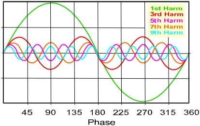
Harmonics in the electrical system results in waveform distortion. In general harmonics are periodic disturbances in voltage and current. Any non-sinusoidal periodic waveform can be considered as a combination of sine waves of specific frequencies, amplitudes and phase angle (Fourier series). In simple terms Harmonics are multiple of the normal main power frequency, like “3rd order” harmonics has got the frequency of 150 Hz and “5th order” has to 250 Hz frequency. Harmonics cause pollution in electrical systems, which may affect the equipment at much larger distances from the origin and if not controlled, can become an expensive proposition.
In a wave shape, only the fundamental component of voltage and current contribute to power translation. The harmonics only load the translation system and cause an increase in apparent power of the source. This non-active power due to harmonics is referred to as distortion power. Power factor correction capacitor banks of such loads are put under considerable stress by the presence of harmonics.
Harmonics are not generated by power generators but are produced by non-linear loads which can be one of the following:-
Loads that make use of semi conductor devices like transistor, thyristor i.e. static rectifiers, AC/DC conversation using SCRs, static frequency converters, and static inverters like :
• Static power converters (AC-DC conversion using SCRs)
• Static rectifiers
• Static frequency convertor
• Static uninterruptible power supplies
• Static induction regulators.
• Variable impedance loads, using electric arcs, arc furnaces, welding units, fluorescent tubes, discharge lamps, Light control, brightness etc.
• Loads using strong magnetising currents saturated transformer, inductance furnaces, reactors etc.
• Office automation products like computers, UPS, printers and fax machine etc.

High level of harmonic distortion can create stress and resultant problems for the utility’s distribution system, the plant’s distribution system, as well as the plants equipment. Equipment shutdown can result from too-high levels of harmonic distortion.
Following is the list of problems that enhanced harmonic distortion can create :
- The capacitors are subjected to a voltage overload and their lifetime is drastically reduced; in fact the voltage drop across the capacitor caused by each of the harmonic currents present must be added to the fundamental voltage. This over voltage is well above 10% when resonance is present, causing the premature dielectric breakdowns.
- Connection of the cap. causes a large increase in the voltage distortion factor THD(V).
- Motors; Reduced motor life, inability to fully load motor.
- The user transformers, wires and loads are affected by this increase in current, which leads to increased I2 R losses and eddy current losses in transformer. This reduces the capacity of transformer resulting into economic loss as well. Apart from this transformer may also be subjected to excessive overheating and saturation.
- This will shorten the life or transformer. When transformer fails, the cost of loss of productivity during emergency repair time far exceeds the replacement cost of transformer itself.
- Interference in computers, microprocessor & solid state controlled equipment because of distorted 240 V supply. Increased neutral to ground voltage may cause hardware problems which may initially look like software problem. International standards recommend that voltage distortion for computer use be limited to maximum of 5% total harmonic distortion (THD-V) and the largest single harmonic not to exceed 3%.
- High voltage distortion shall also be encountered when shifting from mains to emergency generator as they offer high impedance than supply transformer.
- Random switching in deferential relays.
- Large current in neutral wires of power distribution system. This is a real fire hazard as usually phase wires are protected by circuit breakers or fuses.
- Poor power factor: As mentioned earlier the harmonic current caused by non-linear loads do not carry any real power (KW) even though they do increase the volt amperage (KVA). This lowers the power factor at (Pf=KW/KVA) the main distribution transformer. Utilities put penalties on consumers with low p.f, less than 0.9.
- Over heating in fuses resulting in false blowing. False / spurious operations of breakers, which may lead to variation in other characteristics.
- Higher rotation speed of the disks in energy counters due to additional torque resulting in measurement errors.
- Reduction of power generated by UPS.
- Communication / Telephone circuit interference because of induced harmonic noise.
High level of harmonic distortion can create stress and resultant problems for the utility’s distribution system, the plant’s distribution system, as well as the plant’s equipment. Equipment shutdown can result from too-high levels of harmonic distortion.
Following is the list of problems that enhanced harmonic distortion can create :
• The capacitors are subjected to a voltage overload, and their lifetime is drastically reduced; in fact, the voltage drop across the capacitor caused by each of the harmonic currents present must be added to the fundamental voltage. This overvoltage is well above 10% when resonance is present, causing the premature dielectric breakdowns.
• Connection of the cap. causes a large increase in the voltage distortion factor THD(V).
• Motors; Reduced motor life, inability to fully load motor.
• The user transformers, wires and loads are affected by this increase in current, which leads to increased I2 R losses and eddy current losses in the transformer. This reduces the capacity of the transformer resulting in an economic loss as well. Apart from this transformer may also be subjected to excessive overheating and saturation.
This will shorten the life of the transformer. When the transformer fails, the cost of loss of productivity during emergency repair time far exceeds the replacement cost of the transformer itself.
• Interference in computers, microprocessor & solid state controlled equipment because of distorted 240 V supply. Increased neutral to ground voltage may cause hardware problems which may initially look like a software problem. International standards recommend that voltage distortion for computer use be limited to a maximum of 5% total harmonic distortion (THD-V) and the largest single harmonic not to exceed 3%.
• High voltage distortion shall also be encountered when shifting from mains to the emergency generator as they offer high impedance than supply transformer.
• Random switching in deferential relays.
• Large current in neutral wires of power distribution system. This is a real fire hazard as usually phase wires are protected by circuit breakers or fuses.
• Poor power factor: As mentioned earlier, the harmonic current caused by non-linear loads do not carry any real power (K.W.) even though they do increase the volt amperage (KVA). This lowers the power factor at (Pf=KW/KVA) the main distribution transformer. Utilities put penalties on consumers with low p.f, less than 0.9.
• Overheating in fuses resulting in false blowing. False/spurious operations of breakers, which may lead to variation in other characteristics.
• Higher rotation speed of the disks in energy counters due to additional torque resulting in measurement errors.
• Reduction of power generated by UPS.
• Communication / Telephone circuit interference because of induced harmonic noise.
• Variable impedance loads, using electric arcs, arc furnaces, welding units, fluorescent tubes, discharge lamps, Light control, brightness etc.
• Loads using strong magnetising currents saturated transformer, inductance furnaces, reactors etc.
• Office automation products like computers, UPS, printers and fax machine etc.
A non-linear load is a load for which the current consumption does not reflect the supply voltage although the load voltage source is sinusoidal, the current consumption is not sinusoidal. High level of harmonic distortion can create stress and resultant problems for the utility’s distribution system, the plant’s distribution system, as well as the plant’s equipment. Equipment shutdown can result from too-high levels of harmonic distortion.
Following is the list of problems that enhanced harmonic distortion can create:
• The capacitors are subjected to a voltage overload, and their lifetime is drastically reduced; in fact, the voltage drop across the capacitor caused by each of the harmonic currents present must be added to the fundamental voltage. This overvoltage is well above 10% when resonance is present, causing the premature dielectric breakdowns.
• Connection of the cap. causes a large increase in the voltage distortion factor THD(V).
• Motors; Reduced motor life, inability to fully load motor.
• The user transformers, wires and loads are affected by this increase in current, which leads to increased I2 R losses and eddy current losses in the transformer. This reduces the capacity of the transformer resulting in an economic loss as well. Apart from this transformer may also be subjected to excessive overheating and saturation. This will shorten the life of the transformer. When the transformer fails, the cost of loss of productivity during emergency repair time far exceeds the replacement cost of the transformer itself.
• Interference in computers, microprocessor & solid state controlled equipment because of distorted 240 V supply. Increased neutral to ground voltage may cause hardware problems which may initially look like a software problem. International standards recommend that voltage distortion for computer use be limited to a maximum of 5% total harmonic distortion (THD-V) and the largest single harmonic not to exceed 3%.
• High voltage distortion shall also be encountered when shifting from mains to the emergency generator as they offer high impedance than supply transformer.
• Random switching in deferential relays.
• Large current in neutral wires of power distribution system. This is a real fire hazard as usually phase wires are protected by circuit breakers or fuses.
• Poor power factor: As mentioned earlier, the harmonic current caused by non-linear loads do not carry any real power (K.W.) even though they do increase the volt amperage (KVA). This lowers the power factor at (PF=KW/KVA) the main distribution transformer. Utilities put penalties on consumers with low PF, less than 0.9.
• Overheating in fuses resulting in false blowing. False/spurious operations of breakers, which may lead to variation in other characteristics.
• Higher rotation speed of the disks in energy counters due to additional torque resulting in measurement errors.
• Reduction of power generated by UPS.
• Communication / Telephone circuit interference because of induced harmonic noise.
Standards define a Harmonic as “one of the components obtained from the breakdown of a periodic wave (voltage or current) in the Fourier Series”. The order of a harmonic is further defined as “the ratio between the frequency of a harmonic and the fundamental frequency of the network”. Power converters are being used more and more frequently in plants to control motors, medium-frequency ovens, uninterruptible power supplies, etc. These devices regulate the load by modulating the supply voltage, which results in the generation of current harmonics. As they circulate through equivalent impedances in the cables and mains, these harmonics distort the sine waveform of the supply voltage. Characteristic harmonics are defined as “those harmonics produced by static ac/dc converters in ideal theoretical operation”.
The order h of characteristic harmonics is h=mp±1
where m is an integer other than 0 (thus 1, 2, 3, 4,…) and p is the number of solid-state switches of the bridge. Therefore, a converter with six-phase reaction (p=6) generates characteristic harmonics of the 5th and 7th order (m=1), 11th and 13th order (m=2), 17th and 19th order (m=3), etc. In contrast, a converter with twelve-phase reaction (p=12) generates characteristic harmonics of the 11th and 13th order (m=1), 23rd and 25th order (m=2), etc. Non-characteristic Harmonics are defined as “the harmonics produced:
• by an unbalance in the energy network;
• by an asymmetric delay in the triggering angle of the converter;
• by non-linear devices (frequency changers, fluorescent lamps, arc furnaces, electric welders, saturations, …)”.
Due to the current harmonics created by power converters, other parallel loads in the system are also supplied with a distorted voltage: this may cause malfunctioning, especially in electronic parts.
The circulation of current harmonics in the system results in increased losses due to the Joule effect and the effect in the cables, increased hysteretic losses and increased losses due to parasite currents in the iron of transformers and motors.
Installing power factor correction capacitors in the network serves to create a condition of parallel resonance between the equivalent capacitance of the capacitors and the equivalent inductance of the system (which may usually be approximated by calculating the equivalent inductance of the transformer) in correspondence to a frequency fr.
The voltage harmonics present in the system – having a frequency close to the parallel resonance frequency fr – may be amplified even hundreds or thousands of times. For this reason, an extremely high voltage comes to be created at the capacitor terminals, which causes the dielectric to age rapidly and hence significantly shortens the lifespan of the capacitor.
In an industrial plant containing power factor correction capacitors, harmonics distortions can be magnified due to the interaction between the capacitors and the service transformer. This is referred to as harmonic resonance or parallel resonance. It is important to note that capacitors themselves are not the primary cause of harmonics but only aggravate potential harmonic problems. Often, harmonic-related issues do not show up until capacitors are applied for power factor correction.
The impedance of the capacitor decreases with increase in frequency. Capacitor capacity to cancel out harmonic decreases with increase in frequency. This offers a low impedance path to harmonic currents. These harmonic currents added to the fundamental current of capacitors can produce dangerous current overloads on the capacitor.
Each of the harmonic currents causes the voltage drop across the capacitor. This voltage drop is added to the fundamental voltage. Thus in the presence of harmonics higher voltage rating of the capacitor is recommended. This overvoltage can be much above permissible 10% value when resonance is present.
Another critical aspect is the resonance which can occur when p.f. capacitors form the series or parallel resonant circuit with the impedance of supply transformer. If the resonance frequency of this L.C. circuit coincides with one of the harmonic presents, the amplitude of the harmonic current flowing through L.C. circuit is multiplied several times damaging the capacitors, supply transformer and other network components.
It is not uncommon to find multiplication coefficient K of 5-10 and over, but in particular operating condition is beyond all control.


Effect of harmonics on capacitors:
A decrease in capacitors reactance

The capacitor reactance is inversely proportional to the frequency, its curve is reciprocal, and its capacity to cancel out harmonic currents decreases significantly when the frequency increases.
• Parallel resonance or anti-resonance between capacitors and source
• The reactance of the source Xlt is proportional to frequency.
• The reactance of the capacitors Xc is inversely proportion to frequency At the frequency Fr.p, there is parallel resonance or anti-resonance (since the two reactance are equal but opposite) and amplification (F.A.) of the harmonic current in the capacitors and the source (transformer) where:

It is important to note that :
• The higher the source short-circuit power (Scc.) the further the resonance is from dangerous harmonic frequencies
• The higher the load power (P), the lower the harmonic current amplification factor is.

Harmonic Filter
Utilities generate an almost perfect sinusoidal voltage. Harmonics, created by non-linear loads such as variable speed drives, power rectifiers, invertors etc., cause non-linear voltage drops and change the sinusoidal nature of the voltage. When reactive energy is compensated using capacitors, there is a frequency at which the capacitors are in parallel resonance with the power source (high impedance). If the resonant frequency occurs in proximity to one of the harmonic sources, current can circulate between the supply and the capacitors, resulting in high voltage on the line. In this scenario, current levels may exceed the capacitor’s rated current by more than two or three times and can cause the transformer to burn. Resonance can occur at any frequency; however, in most cases, current harmonic sources exist at the 5th, 7th, 11th, & 13th harmonic. With ACTIVECOMP to cope with Harmonics, the following solutions can be offered.
De-tuned Systems
In de-tuned systems, reactors are installed in series with the capacitors and prevent resonance conditions by shifting the capacitor/network resonance frequency below the first dominant harmonic (usually the 5th). The graph on the next page shows the capacitor/network amplification factor and the shifting of the resonance frequency from near the 5th harmonic to near the 3rd harmonic.

Tuned Systems
If Harmonic Filter is needed, on top of resonance prevention, tuned reactors are applied. The capacitor/reactor filter is tuned to absorb particular harmonic and reduce the Total Harmonic Distortion (THD). The bottom graph on the left shows harmonic filtration using the tuned system: the voltage THD was reduced by more than 70% (8.8% to 2.5%) and the dominant harmonics (5th and 11th) were reduced by 75%.
Tuned ACTIVECOMP vs Active Harmonic Filters
Active filters inject currents to the network in anti-phase to the harmonics. This technology is an expensive solution and increases system losses (3% typical). For applications with one or two dominant harmonics, Neptune’s Tuned ACTIVECOMP is the preferred choice, both technically and economically, effectively minimising system losses and reducing the Total Harmonic Distortion (THD).
Harmonics Theory
Introduction: The term “harmonic” refers to sinusoidal components at a frequency which is a multiple (2,3,4,5…) of the fundamental.
Harmonic source frequencies (fn) can be expressed as:
fn=fo (PxN ± 1)
Where:
fo = Fundamental frequency
P = Number of rectifier/switching elements
N=Integer number 1, 2, 3, ….
Example: Six pulse rectifier (P=6)
fn = 5, 7, 11, 13, 17, 19 …


The Problem
When the reactive energy is compensated using capacitors, there is a frequency at which the capacitors are in parallel resonance with the mains (high impedance). If the resonance frequency of the capacitors-mains occurs close to one of the harmonic sources, the current can circulate between the supply and the capacitors. This results in high voltage on the line and the capacitor current may exceed the rated current by more than double or triple its value.


The Solution
Resonance can occur on any frequency; however, in most cases, the current harmonic sources exist at the 5th, 7th, 11th and 13th harmonic. The ACTIVECOMP custom-designed reactors, in series with the capacitors, prevent resonance by shifting the capacitor/network resonance frequency below the first dominant harmonic (usually the 5th)


There are three choices when deciding where to apply harmonic filters:
- At the Load
- At the transformer or
- On the Primary Distribution.
SOLUTIONS
NAAC ENERGY CONTROLS (P) LIMITED can offer the following solutions for mitigation of Harmonics.
- Detuned Filtration System
- Tuned Harmonic Filtration System
- Hybrid Harmonic Filtration System
- Active Harmonic Filters
Depending on the application, the type of harmonic filtration will differ. Contact our Corporate Office in Delhi-NCR or Regional Offices for further information regarding Harmonic Filter or Load/Harmonic Analysis at your site.
Electrical fires pose a major threat to the industrial infrastructure. The primary reason cited for electrical fires is a short circuit but the causes of an electrical fire go beyond that. In many cases the reason a short circuit happens is linked to poor power quality. Electrical fires in most cases is the consequence of overheating in the electrical networks. Due to the unwanted harmonics, which are basically higher frequency currents, heat is generated in the electrical system. Non-linear loads like computers, office equipment, switched-mode power supply and transformers on low loads generates 3rd order harmonic currents. This 3rd harmonic adds on to the neutral in a three phase system causing the neutral conductor to overheat. This heating overtime causes damage to the insulation leading to potentially hazardous situations.
Overloading can occur due to poor power factor, which leads to higher kVA being drawn at a constant voltage causes higher current flow and heating which can be potentially dangerous.
Extended exposure to voltage surges in the network can lead up to the catastrophic failure of the critical electronic equipment along with its wiring. The wiring insulation of an equipment fails due to heating and cooling after the voltage surges, therefore increasing the risk of sparking and a fire.

